Sistership Corazón under sail, a Searunner 34 in Mexico
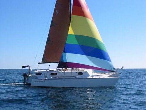
Searunner 34 CORAZÓN sailing in the Sea of Cortez, México
Tuesday, March 25, 2014
ETAK will be getting a brand-new Shipmate two burner propane stove! No longer in business, the company that made the Shipmates has been out of production for a long time. The original stove is in a sad state of needing a total refurbishment, but luckily I found a new one, still in the original shopping box that I will be purchasing in person in about a week. It should slip right into the same galley spot on the starboard side as the old one. I will put up some photos once I have it.
Thursday, July 14, 2011
Bow Nose Primered!
I had no idea how much work simply adding the nose section back to the main hull bow would be. It has robbed me of time for other projects, but is finally ready for paint. Like all fiberglass on Etak that is exposed to UV, I put a dark primer coat over the bare epoxy work before going to basic white. And, what a difference paint makes! Unfortunately I don't have any pictures of the white over the primer to post, only the primered part of the bow.
I was lucky to get several gallons of Z-Spar U109 two part primer at a real low price awhile back, so I bought all that the local marine chandlery had in stock and kept it for future use. The mix ratio is 3 to 1, and the paint is typically thick and more dense than water. The hardener, however, is about like water , so I could not use my gram scale to weigh and get the correct ratio. All my mixing containers are slope-sided, so measuring depth in the containers would not work either. What to do? I used the weighing scale and water to determine where 3-to-1 came on the side of the containers and marked them accordingly. It then was easy to fill the big cup to the paint line for three parts, then add the one part of hardener.
The directions say that at 70 degrees F and 50% humidity, there is an eight hour pot life to the mix. Yesterday I mixed a whole gallon of the primer to cover as much of the topsides and a little of the hull sides as I could get done in my window of time. Temperature was around 72-73 degrees F inside the cabin, but the humidity was well below the 50% range, and the sun was intense. That stuff started kicking off too fast! I did manage to use up the whole gallon before it went off, but toward the end, even with reducer added, it was getting harder and harder to roll on. Fortunately, it is very sand-able, and the orange peel I left behind will sand down very smooth. That simply means more of my favorite work later on: sanding!
 Here, above, is the starboard side before primer.
 And here is the port side view. Note the fairing in of the 1/8" door skin plywood (the trapezoid shape below the headstay). The epoxy filler will hide the ridge caused by the wood standing proud of the subsurface skin of the hull).
 Port side view again with primer rolled on.
 This shot shows the starboard side getting the primer treatment. Note the train on the long trestle laden with double stacked cargo containers. these trains cross roadways all around us, and blast their horns four times for each crossing. The sound is not only deafening, but actually may do hearing damage. We really want to get away from all the trains in this area. The plus of this industrial part of the greater Los Angeles/Long Beach harbor is that we can actually do work on our boat here in the water as long as we are careful not to get sanding dust in the water. There are not many marinas around where we would be able to do all the major refit chores we are doing, so we stay put and work away.
I was lucky to get several gallons of Z-Spar U109 two part primer at a real low price awhile back, so I bought all that the local marine chandlery had in stock and kept it for future use. The mix ratio is 3 to 1, and the paint is typically thick and more dense than water. The hardener, however, is about like water , so I could not use my gram scale to weigh and get the correct ratio. All my mixing containers are slope-sided, so measuring depth in the containers would not work either. What to do? I used the weighing scale and water to determine where 3-to-1 came on the side of the containers and marked them accordingly. It then was easy to fill the big cup to the paint line for three parts, then add the one part of hardener.
The directions say that at 70 degrees F and 50% humidity, there is an eight hour pot life to the mix. Yesterday I mixed a whole gallon of the primer to cover as much of the topsides and a little of the hull sides as I could get done in my window of time. Temperature was around 72-73 degrees F inside the cabin, but the humidity was well below the 50% range, and the sun was intense. That stuff started kicking off too fast! I did manage to use up the whole gallon before it went off, but toward the end, even with reducer added, it was getting harder and harder to roll on. Fortunately, it is very sand-able, and the orange peel I left behind will sand down very smooth. That simply means more of my favorite work later on: sanding!


Wednesday, June 22, 2011
Main Hull Bow Work Continues
I had no idea that simply removing the headstay chainplate would evolve into such a long-term project. But it did! Now, the work is getting closer to being all done, thank goodness. I added another piece of wood to the edge on both sides and now Etak has a more typical Searunner look to her, at least on this middle bow.
The summer solstice just happened here in the Northern Hemisphere a day ago, and the summer sun is certainly warming things up here in the greater Los Angeles--Long Beach, California area. By mid afternoon until around 5:00 p.m., it is getting warm. The heat is not too bad, but the intensity of the sun is. Having had both basal cell and squamous cell carcinoma removed from my back and neck, I am cautious to protect myself as much as I can from the damaging effect of the UV A and B. Thus, the long-tailed and big billed fisherman's hat in one of the photos below.
Yesterday, June 21, I put the pulpit on temporarily to ascertain its location and fit. I don't have photos of it on the bow yet, but will soon.

In this photo above, I am adding the second deck extension or overhang from a strip of furring lumber from Home Depot. I could not find any vertical grain Douglas Fir. There was plenty of maple, poplar, and other hardwoods, but only rough 2 x 4's in fir along with other house-building sizes. A search through the pile of 1 x 2 furring strips yielded a couple with good grain and minimal knots. This one got split from one end to the other on the table saw tapering from about 1/2" to almost full width. The remaining half will go to the port side of the bow.

 Here in these two shots above, you can see the foam filling that has been faired, then the add-on of some 1/8" door skin luan held in place with drwall galvanized grabber screws. They will be removed after the epoxy cures. This starboard side has the luan attached flush with the hull. The port side is attached proud of the hull (below) to be faired in with bog since it is slightly off center on that side.


In this photo above, you can see the second furring strips epoxied to the first strips.

Rough fairing in has begun.

Getting closer to the final stage!
Soon it will be time to return home to Oregon. The amount of work that must be done to leave Etak ready for inclement weather is a bit overwhelming. As each day passes, I worry more and more if we will be able to get all the things done before we depart. Here it is 6:00 a.m. and I am posting to this blog after having been up since 3:00, and before I know it, I must head for the harbor and another day of work. Yesterday I removed the Farymann engine from its compartment on the port side of the centerboard trunk. The little (but too heavy) chunk of iron sits in the galley just below where the oven will be. The companionway ladder is in place, but ony barely so with the diesel beast occupying much of the floor space. Today's goal is to get into the now empty engine "room" and sand away until I am happy with the surfaces prior to doing some much needed epoxy work. The ultimate goal is to get a good coat of paint in this area with the engine removed. I will try to get some pictures today of the engine in the galley and the empty area before work begins.
Having the permanent sole of the cockpit out, access to this area is much better. In fact so much better that I am planning on adding the new sole to be non-permanent but totally waterproof. It will involve a gasketing system and bolt down similar to how valve covers are installed on automobile engines. Having that access from above simplifies engine removal and replacement so much that engineering a gasketed-down sole is worth the effort. That little (but heavy) diesel still comes out into the galley via a strong aluminum tube with traveler track and car bolted it. I lift the engine from its bed with a turnbuckle to the traveler car and slide the beast aft to the opening into the galley. Then with a 4 x 4 timber or similar across the companionway sliders, I use a block and tackle arrangement to hoist the engine enough to relieve the load on the turnbuckle and swing it to the sole of the galley. The access from above is simply for me to lean into and attach the various items used to move the engine, remove the alternator (it makes it a little wide to come out through the opening into the galley), and have a bit more work room. In a vessel this small, the engine cannot be lifted out through this sole opening as it is only about a foot wide.
The summer solstice just happened here in the Northern Hemisphere a day ago, and the summer sun is certainly warming things up here in the greater Los Angeles--Long Beach, California area. By mid afternoon until around 5:00 p.m., it is getting warm. The heat is not too bad, but the intensity of the sun is. Having had both basal cell and squamous cell carcinoma removed from my back and neck, I am cautious to protect myself as much as I can from the damaging effect of the UV A and B. Thus, the long-tailed and big billed fisherman's hat in one of the photos below.
Yesterday, June 21, I put the pulpit on temporarily to ascertain its location and fit. I don't have photos of it on the bow yet, but will soon.

In this photo above, I am adding the second deck extension or overhang from a strip of furring lumber from Home Depot. I could not find any vertical grain Douglas Fir. There was plenty of maple, poplar, and other hardwoods, but only rough 2 x 4's in fir along with other house-building sizes. A search through the pile of 1 x 2 furring strips yielded a couple with good grain and minimal knots. This one got split from one end to the other on the table saw tapering from about 1/2" to almost full width. The remaining half will go to the port side of the bow.


In this photo above, you can see the second furring strips epoxied to the first strips.

Rough fairing in has begun.

Getting closer to the final stage!
Soon it will be time to return home to Oregon. The amount of work that must be done to leave Etak ready for inclement weather is a bit overwhelming. As each day passes, I worry more and more if we will be able to get all the things done before we depart. Here it is 6:00 a.m. and I am posting to this blog after having been up since 3:00, and before I know it, I must head for the harbor and another day of work. Yesterday I removed the Farymann engine from its compartment on the port side of the centerboard trunk. The little (but too heavy) chunk of iron sits in the galley just below where the oven will be. The companionway ladder is in place, but ony barely so with the diesel beast occupying much of the floor space. Today's goal is to get into the now empty engine "room" and sand away until I am happy with the surfaces prior to doing some much needed epoxy work. The ultimate goal is to get a good coat of paint in this area with the engine removed. I will try to get some pictures today of the engine in the galley and the empty area before work begins.
Having the permanent sole of the cockpit out, access to this area is much better. In fact so much better that I am planning on adding the new sole to be non-permanent but totally waterproof. It will involve a gasketing system and bolt down similar to how valve covers are installed on automobile engines. Having that access from above simplifies engine removal and replacement so much that engineering a gasketed-down sole is worth the effort. That little (but heavy) diesel still comes out into the galley via a strong aluminum tube with traveler track and car bolted it. I lift the engine from its bed with a turnbuckle to the traveler car and slide the beast aft to the opening into the galley. Then with a 4 x 4 timber or similar across the companionway sliders, I use a block and tackle arrangement to hoist the engine enough to relieve the load on the turnbuckle and swing it to the sole of the galley. The access from above is simply for me to lean into and attach the various items used to move the engine, remove the alternator (it makes it a little wide to come out through the opening into the galley), and have a bit more work room. In a vessel this small, the engine cannot be lifted out through this sole opening as it is only about a foot wide.
Friday, June 10, 2011
ETAK's Rhinoplasty
When I learned from co-designer John Marples that older Searunners with the original 304 stainless steel chain-plates and fittings should have them changed out for more corrosion resistant 316 SS, I began the process of following his advice. He generously send a copy of the plans page with all the dimensions of the various fittings.John has made this information available to all Searunner owners. So, if you have a Searunner and want the updated page, contact John directly via his website.
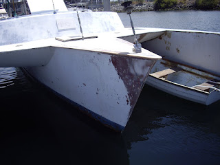
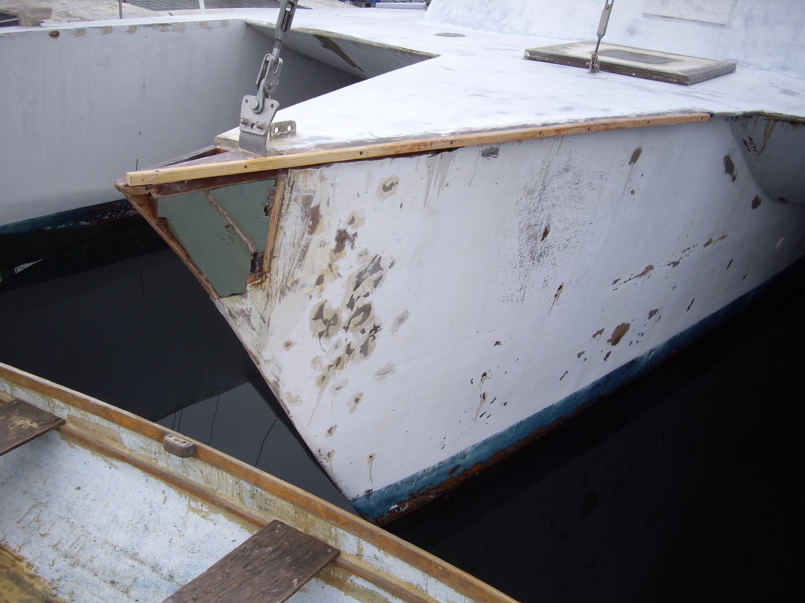
One of the most difficult to get to was the chain-plate of the head stay. It is back about a foot from the tip of the bow nose. With nephew Frank, we attacked the job with Frank's Saws All (sp?). Here is a head-on picture of the bow with the chunk of nose whacked off:

Six 3/8" bolts and bedding compound held the old chain-plate in place. The nuts were inside and barely accessible through a large circular hole in the first frame. I just was able to get a wrench in and on the bolts at full-arm's length. Doreen was able to hold the bolts from turning as she stood in the dinghy when it was placed in front of the bow at 90 degrees to it.
After removing the old chain-plate and bolts, I needed to seal the old plywood prior to installing the new 316SS plate. First I added 17 oz bi-axial fiberglass cloth and epoxy resin in a couple of layers as seen here:

 Now the area has been sanded and the holes drilled through for the new chain-plate.
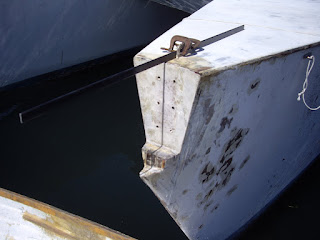
 This picture above shows the new plate in place and bedded with 3M 4200.
 In this photo above you can see that I routered out to the requisite depth a section to cover the new plate on the bow. Obviously really a rough job, but I did not have a guide, just the "good-eye" approach (it obviously wasn't all that good!).
 Here is that same ply plate covering the new chain-plate with the nuts exposed. It was much easier to attach the chain-plate with the nuts on the outside! This ply cover is epoxied on but should anyone ever need to get to the nuts, they will be (somewhat) accessible. Some additional 3M 4200 has since been added to cover the nuts and seal the area from any possible intrusion of water (highly unlikely once everything is covered and sealed).
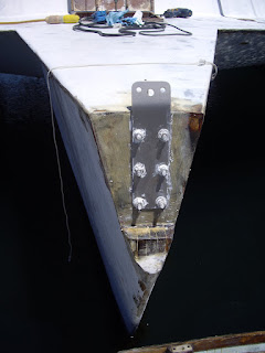
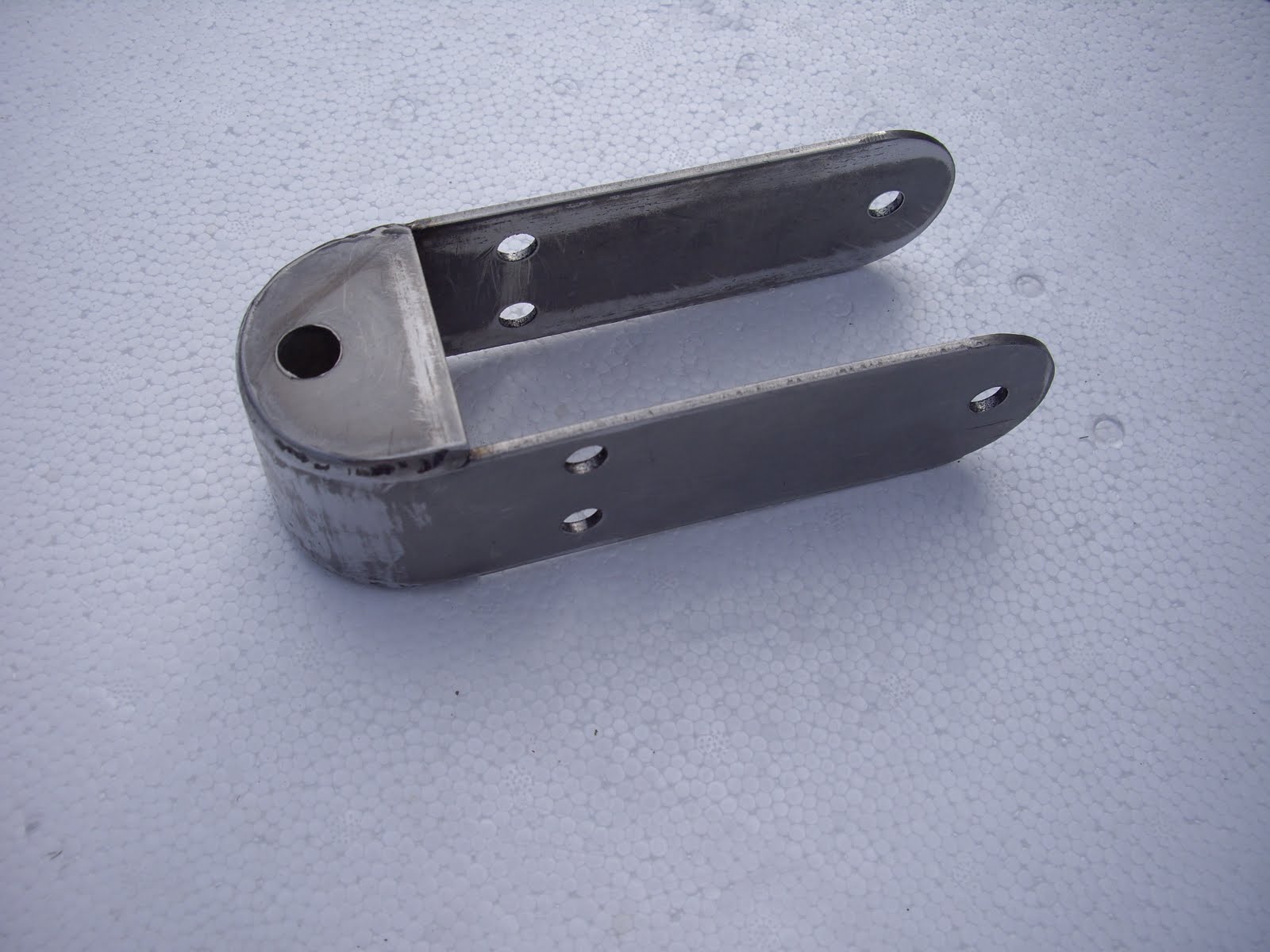
 Above in this photo, you can see the 3/4" plywood cover from a different angle. Note the 1/4" 316SS attachment to the chain-plate. On the plans page John Marples sent, it calls for 3/16" SS, but he added a hand-written addendum that it could be 1/4" thickness. Wanting the extra strength of the thicker plate and contemplating adding synthetic standing rigging as Corazón has, I fabricated this additional piece in 1/4" 316 SS for the Colligo dead-eye lashing terminator. Still missing is one 1/2" bolt to add to the two 3/8" bolts holding the small plate to the chain-plate.
In order to put the rest of the nose one, I needed to make up some sort of add-on piece to bring the bow back to a point. Some scrap pieces of mahogany and some more 3/4" plywood get epoxy coated prior to assembly (below)

Assembled!


Of course, she could not have a complete nose job without some "plastic" surgery, so the next step was to add some plastic to her nose (plastic in the form of foam):

 Believe me! The nurse almost got fired after such a bungled taping job!
The surgeon got out his scalpel and went to shaping the new nose:
 Note above that a strip of 3/4" by about 1" trim has been added to the port side of the bow. I noticed that the plywood top of the entire bow is off on the overhang on this port side, so I am adding a piece in to balance the two sides dimensionally. The starboard side will get a much small add-on and the typical Searunner clipper bow and flare will be enhanced over the original point of the bow which came to a very narrow and sharp beak-like point.

One of the most difficult to get to was the chain-plate of the head stay. It is back about a foot from the tip of the bow nose. With nephew Frank, we attacked the job with Frank's Saws All (sp?). Here is a head-on picture of the bow with the chunk of nose whacked off:

Six 3/8" bolts and bedding compound held the old chain-plate in place. The nuts were inside and barely accessible through a large circular hole in the first frame. I just was able to get a wrench in and on the bolts at full-arm's length. Doreen was able to hold the bolts from turning as she stood in the dinghy when it was placed in front of the bow at 90 degrees to it.
After removing the old chain-plate and bolts, I needed to seal the old plywood prior to installing the new 316SS plate. First I added 17 oz bi-axial fiberglass cloth and epoxy resin in a couple of layers as seen here:


In order to put the rest of the nose one, I needed to make up some sort of add-on piece to bring the bow back to a point. Some scrap pieces of mahogany and some more 3/4" plywood get epoxy coated prior to assembly (below)

Assembled!


Of course, she could not have a complete nose job without some "plastic" surgery, so the next step was to add some plastic to her nose (plastic in the form of foam):


The surgeon got out his scalpel and went to shaping the new nose:

Saturday, May 21, 2011
Another Can of Worms
After getting all the teak runners off the cockpit sole, epoxy coating the old plywood, and meticulously sealing all the staple holes, I found the sole halves on both sides of the now-open centerboard trunk top were not epoxied down to the frames they rested on! They were merely put down with a caulking compound that still held them, but with just a little lifting, I took them both off by hand. No wonder water could migrate into areas it should not have. The port side of the trunk had the sole screwed along the trunk edge, but the starboard side just lifted right off. So, the new plan is to replace these pieces of old ply with new. Here is how the area looks without the soles:
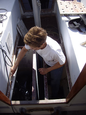 Doreen is scraping the debris off the support stringers. Her left hand is on the starboard side of the open trunk top. This picture shows just how deep the stowage area is on the starboard side with the sole of the cockpit removed. The port side houses the Farymann diesel engine covered in black plastic and not visible.
Seen from a different angle, here is that same compartment now partially sanded preparatory for new primer and paint before putting the lid on it (the new cockpit sole):
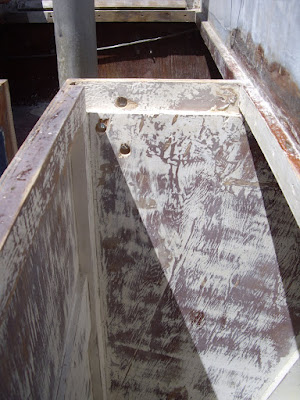
The three 3/4" inch holes at the bulkhead are to be filled with epoxy mix and re-drilled for adding a plate to cover the front of the trunk from the sole level down about 14" to the sub-sole area where the mast base is located.
 Above is another view of the trunk from forward of the bulkhead seen in the preceding photo. You are looking aft at both compartments on both sides of the trunk. The white tube on the port side is a support piece with a track bolted to it with a traveler car on it. Hanging from the car there is a turnbuckle which attaches to a lift point on the engine for sliding it fore and aft in the compartment along its bed. By lifting it with the turnbuckle from the bed, it can be pulled aft to the opening at the galley. From there with a halyard from the mast top it is lifted up and into the cockpit for removal and replacement. I have down it a couple of times now with one other person and it works well despite its weight.
Very visible in this photo are the six holes in the upper part of the cross beam. Below are four more holes that do not penetrate completely. Nuts for the cover plate will be bedded in these partial holes for removal of the vertical cover plate for removal of the centerboard. It too can be hoisted out of the trunk with the main halyard once this opening and the steering mechanism is removed. Therefore, all the steering items attached here must be removable but securely attached to the front of the centerboard trunk. That is the engineering project I am immersed in right now.
Here is the front plate that covers the vertical part of the trunk and will mate with the holes shown on the bulkhead that supports the steering mechanism. I call this piece of 3/4" ply "Mr. Tee" for obvious reasons. Note the edges all have been coated with epoxy and filler to seal the plywood end-grain. The over-sized holes will get epoxy bog and be re-drilled for the bolts that will secure it to the bulkhead. This panel will be removable and serve as the main attachment of the steerer.

As can be seen in the picture below, the blocks that control the up and down of the centerboard need access and inspection for appropriate replacement. This old Schaefer cheek block was removed from the aft end of the trunk. The sheave still turned, but most of the aluminum plate on the top side of the unit has corroded away. Three of the four attachment bolts held, but one fell off in my hands when I removed it. To get to the unit, there is a small oval hole just above the block that was covered over with a large piece of 3/8" plywood secured with some of the same white mastic that held down the soles. Chisel and hammer work and I got the plywood off for access to the inspection port. Then a few sharp blows with my hammer and the small hand-size piece of plywood came out. Now I must build a new and better inspection port that will allow easy and frequent access to the new cheek block once it is in place. The plans call for a minimum 3/8" axle for the sheave, and this one is perhaps 1/4" only. The new one will be overkill with no aluminum anywhere! The waterline currently is just below this block but underway there is a lot of water that moves around in the trunk and keeps this metal wet with salt water. Ideally a small zinc anode should be added to the block.

Another view of the corroded old thing: Amazing it still held when i pulled the board down!

So, with about 20 different projects going on at once, the primary focus right now is to get the new sole in place covering the engine and stowage compartments on both sides of the trunk. In order to accomplish this goal, I need to finish sanding and painting in the compartments now that they are more accessible with the sole on both sides of the trunk removed.
Keeping the dream alive and the enthusiasm going is paramount to the success of the overall project. I have leaned heavily on posts from Mark Johnson of the Searunner 34 Delphys. Mark has been exceedingly helpful with ideas, his experience going down this same road. His photos on the Searunner thread of the Cruisers Forum is filled with good advice, excellent photos, and lots of detail. Others have been helpful in keeping me on the right track. John Marples was very quick in sending me several of the pages to the plans i requested. Dave Weber came by for a few days and shared some of his thoughts about the 34's he has seen in his travels. Mike Lenemen is in the wings as soon as I need him for some rigging expertise. Roy Mills helped with some thoughts on bedding compounds when I called him on the phone. It is this large multi-hull community and Searunner sailors specifically that are a viable part of keeping me going. Jack Molan has been a world of help with his information on synthetic standing rigging and all the photos he has of his SR-34 Corazón in Mexico. A number of vendors have been helpful for much of the on-line purchasing I do of epoxy, fiberglass cloth, peel ply, boat hardware, and myriad other items that go into such a major project as refurbishing and re-outfitting an old boat.
Without the continuous positive help of my first mate and wife Doreen, this effort would not reach fruition. We share a common goal of getting Etak cruise-worthy. Her preparation of nutritious food and logistic help is vital to the process. Doing it alone I would find myself hard pressed to work hard, then eat well after all the work.
We are fortunate to have lots of boat stuff stored in a few locations. My nephew and niece, a mere 12 miles away have several crates of boat goodies. Our friend Al and his wife have a storage shed full of cushions, sails, lines, chain and anchors that would be impossible to keep on board and still be able to work on the boat.

Seen from a different angle, here is that same compartment now partially sanded preparatory for new primer and paint before putting the lid on it (the new cockpit sole):

The three 3/4" inch holes at the bulkhead are to be filled with epoxy mix and re-drilled for adding a plate to cover the front of the trunk from the sole level down about 14" to the sub-sole area where the mast base is located.

Very visible in this photo are the six holes in the upper part of the cross beam. Below are four more holes that do not penetrate completely. Nuts for the cover plate will be bedded in these partial holes for removal of the vertical cover plate for removal of the centerboard. It too can be hoisted out of the trunk with the main halyard once this opening and the steering mechanism is removed. Therefore, all the steering items attached here must be removable but securely attached to the front of the centerboard trunk. That is the engineering project I am immersed in right now.
Here is the front plate that covers the vertical part of the trunk and will mate with the holes shown on the bulkhead that supports the steering mechanism. I call this piece of 3/4" ply "Mr. Tee" for obvious reasons. Note the edges all have been coated with epoxy and filler to seal the plywood end-grain. The over-sized holes will get epoxy bog and be re-drilled for the bolts that will secure it to the bulkhead. This panel will be removable and serve as the main attachment of the steerer.

As can be seen in the picture below, the blocks that control the up and down of the centerboard need access and inspection for appropriate replacement. This old Schaefer cheek block was removed from the aft end of the trunk. The sheave still turned, but most of the aluminum plate on the top side of the unit has corroded away. Three of the four attachment bolts held, but one fell off in my hands when I removed it. To get to the unit, there is a small oval hole just above the block that was covered over with a large piece of 3/8" plywood secured with some of the same white mastic that held down the soles. Chisel and hammer work and I got the plywood off for access to the inspection port. Then a few sharp blows with my hammer and the small hand-size piece of plywood came out. Now I must build a new and better inspection port that will allow easy and frequent access to the new cheek block once it is in place. The plans call for a minimum 3/8" axle for the sheave, and this one is perhaps 1/4" only. The new one will be overkill with no aluminum anywhere! The waterline currently is just below this block but underway there is a lot of water that moves around in the trunk and keeps this metal wet with salt water. Ideally a small zinc anode should be added to the block.

Another view of the corroded old thing: Amazing it still held when i pulled the board down!

So, with about 20 different projects going on at once, the primary focus right now is to get the new sole in place covering the engine and stowage compartments on both sides of the trunk. In order to accomplish this goal, I need to finish sanding and painting in the compartments now that they are more accessible with the sole on both sides of the trunk removed.
Keeping the dream alive and the enthusiasm going is paramount to the success of the overall project. I have leaned heavily on posts from Mark Johnson of the Searunner 34 Delphys. Mark has been exceedingly helpful with ideas, his experience going down this same road. His photos on the Searunner thread of the Cruisers Forum is filled with good advice, excellent photos, and lots of detail. Others have been helpful in keeping me on the right track. John Marples was very quick in sending me several of the pages to the plans i requested. Dave Weber came by for a few days and shared some of his thoughts about the 34's he has seen in his travels. Mike Lenemen is in the wings as soon as I need him for some rigging expertise. Roy Mills helped with some thoughts on bedding compounds when I called him on the phone. It is this large multi-hull community and Searunner sailors specifically that are a viable part of keeping me going. Jack Molan has been a world of help with his information on synthetic standing rigging and all the photos he has of his SR-34 Corazón in Mexico. A number of vendors have been helpful for much of the on-line purchasing I do of epoxy, fiberglass cloth, peel ply, boat hardware, and myriad other items that go into such a major project as refurbishing and re-outfitting an old boat.
Without the continuous positive help of my first mate and wife Doreen, this effort would not reach fruition. We share a common goal of getting Etak cruise-worthy. Her preparation of nutritious food and logistic help is vital to the process. Doing it alone I would find myself hard pressed to work hard, then eat well after all the work.
We are fortunate to have lots of boat stuff stored in a few locations. My nephew and niece, a mere 12 miles away have several crates of boat goodies. Our friend Al and his wife have a storage shed full of cushions, sails, lines, chain and anchors that would be impossible to keep on board and still be able to work on the boat.
Tuesday, May 10, 2011
Work in Progress, May 2011
Despite the lack of blog entries, work has been progressing. We are usually too tired and it is too late by the time we finish working, clean up, prepare dinner, wash the dishes, check email, and get ready for bed. Part of the problem is that we are not allowed to use our van-camper for sleeping in the parking lot. So we cook within, rest there, and generally relax in the Roadtrek. But we sleep in the double berth (starboard side in our SR-34) and attempt to keep it free of sawdust, epoxy, sandpaper, and all that goes with working on the vessel.
A number of distinct projects are on-going at any one time. The most recent is the revamping of the sole of the center cockpit. When John Marples and Jim Brown designed the 34, they keep to the center cockpit and deep centerboard of earlier Searunner models. The centerboard trunk serves as the step for the mast and the sole of the cockpit is installed on top of the trunk. The plans call for a removable cap to the trunk as part of the sole. Etak never get this cap. The plywood for the sole has teak runners running fore and aft that serve to channel any water in the cockpit to the drainage area just forward of the pedestal. This picture should help visualize what I am attempting to explain:
 Those holes in the forward part of the sole is for drainage into the sub-sole area,a bout 12 inches below what you see here. There are holes in both sides of the hull well above the water line that allow the sub-sole area to get rid of the water.
 In this photo you can see there are now holes beside and aft of the pedestal. They would drain into the lockers below since there is no sub-sole here.
 After removing the pedestal, I stripped off the teak runners in order to get to the very old plywood that is deteriorating with over thirty years of exposure to the elements. The next job is to sand out the worst of the wood, then begin the epoxy treatment to preserve what is still good.
 I started with only epoxy resin and cotton swabs to get the liquid down into all the staple and screw holes.
 Looking aft you can see the cut out of the top of the centerboard trunk. The two circles about 2" in diameter are when the old diesel and water fill openings used to be. They will be filled with bog and capped off. I have not decided where the new ones will go yet, but they can be added anytime after the sole is complete even if I choose to place them where they were before.
 This is how epoxy darkens up old, dry wood. One coat of resin only is now covering the portion of the cockpit sole prior to other coats and fiberglass cloth.
I hope to add in some photos of the other jobs we are working on as we jump from one to another.
It will be a long time yet before we can hoist any sails, but progress is being made!
A number of distinct projects are on-going at any one time. The most recent is the revamping of the sole of the center cockpit. When John Marples and Jim Brown designed the 34, they keep to the center cockpit and deep centerboard of earlier Searunner models. The centerboard trunk serves as the step for the mast and the sole of the cockpit is installed on top of the trunk. The plans call for a removable cap to the trunk as part of the sole. Etak never get this cap. The plywood for the sole has teak runners running fore and aft that serve to channel any water in the cockpit to the drainage area just forward of the pedestal. This picture should help visualize what I am attempting to explain:


I hope to add in some photos of the other jobs we are working on as we jump from one to another.
It will be a long time yet before we can hoist any sails, but progress is being made!
Sunday, April 10, 2011


It sure feels good to have this much more work done. Many thanks to Mike Hurd of Hurd's Hardware in Harrisburg, OR for the fine work in finishing up the fabrication of these stainless items that I had pre-fabbed a few months back. Mike had to get some 316 SS rod for the welding of this grade of stainless.
Lots of bits and pieces are accumulating for the continued refit: Moen sink fixtures for the galley and head vanity, primary winches off eBay, a gallon of experimental soy-based paint, ABS plastic for headliner material, and many other items.
In the works is interior LED lighting from a source that has developed some unique products for RVs and boats. The designer and I are communicating via email. Low battery drain and sufficient lighting in both soft white and night-vision red are in the works. Details to follow as progress develops.
Subscribe to:
Posts (Atom)